


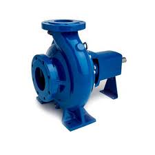
Horizontal Centrifugal Pump
Horizontal Centrifugal Pump | Industrial Fluid Transfer Solution
Engineering Quick Facts
Flow Capacity: Up to 500 m³/h (2,200 GPM)
Head Range: Up to 160 m (525 ft)
Casing Pressure: Rated up to 1.6 MPa (230 psi)
Execution Standards: ISO 2858 / ASME B73.1 dimensional configurations available
Product Overview & Engineering Principle
The horizontal centrifugal pump relies on rotational kinetic energy transferred from an impeller to increase fluid velocity and pressure. Liquid enters axially through the suction nozzle into the impeller eye, flows radially outward into the volute casing, and converts velocity head into static pressure head.
Mounted on a rigid structural steel baseplate, this horizontal layout physically separates the pump wet end from the driver. This configuration provides direct access for alignment checks, simplifies coupling maintenance, and maintains lower vibration amplitudes compared to inline vertical designs.
Technical Specifications & Material Options
Material compatibility prevents premature corrosion and erosion when handling aggressive chemicals, abrasive slurries, or utility water.
Hydraulic & Mechanical Parameters
• Discharge Diameter: 32 mm to 300 mm (1.25 in to 12 in)
• Operating Temperature Range: -20°C to +180°C (extended ranges require auxiliary cooling jackets)
• Rotational Speed: 1450 rpm / 2900 rpm (50 Hz) or 1750 rpm / 3500 rpm (60 Hz)
• Shaft Sealing: Single or double mechanical seals conforming to API 682 / DIN 24960, or canned magnetic drive.
Materials of Construction
|
Component |
Standard Material |
Optional / Severe Duty Material |
|
Casing / Volute |
ASTM A48 Class 35B (Cast Iron) |
CF8M (316 Stainless Steel), CD4MCu (Duplex) |
|
Impeller |
ASTM A351 CF8 (304SS) |
Hastelloy C, Titanium, Bronze |
|
Shaft |
AISI 420 |
AISI 316, 17-4PH |
|
Wear Rings |
Bronze / Cast Iron |
Stellite faced / Silicon Carbide |
Manufacturing Process & Quality Control
Dimensional stability and material integrity originate from strict foundry and machining protocols.
Casting & Metallurgy: Impellers are produced via investment casting to maintain hydraulic profile tolerances within ± 0.5 mm and minimize skin friction losses. Pressure-retaining casings undergo hydrostatic proof testing at 1.5x maximum allowable working pressure (MAWP) prior to finish machining.
CNC Machining: Shafts are turned on precision CNC lathes to control journal diameters and keep radial runout under 0.02 mm, preventing excessive shaft deflection that degrades mechanical seal faces.
Dynamic Rotor Balancing: Fully assembled impellers and shafts undergo dynamic balancing to ISO 1940 Grade 6.3 (Grade 2.5 available on request) to eliminate mechanical unbalance forces.
Performance Testing: Factory Acceptance Testing (FAT) is performed on a closed-loop test bench measuring flow, head, absorbed power, and NPSH in accordance with ISO 9906 Grade 2B standards. Certified test curves ship with every production lot.
Application Guide & Selection Matrix
Hydraulic selection requires matching system resistance curves to the pump's Best Efficiency Point (BEP).
|
Industrial Sector |
Typical Fluid Handled |
Recommended Configuration |
|
Chemical Processing |
Acids, caustic solutions, organic solvents |
316SS / Duplex Stainless Steel, Carbon/Silicon Carbide mechanical seal |
|
Water & Wastewater |
Effluent, raw water, municipal supply |
Cast iron casing with bronze trim, grease-lubricated heavy-duty bearings |
|
HVAC & District Cooling |
Chilled water, condenser water loops |
End-suction frame-mounted layout, cast iron construction |
|
General Manufacturing |
Coolant loops, washdown systems, boiler feed |
Standard end-suction layout with IP55 TEFC motor |
Vendor Evaluation & Compliance
Procurement audits rely on verifiable manufacturing and quality documentation:
Quality Systems: ISO 9001:2015 certified manufacturing facility, CE compliance for machinery safety, and optional ATEX certification for classified hazardous zones (Zone 1 / Zone 2).
Material Traceability: Material Test Reports (MTRs) provided per EN 10204 3.1 for all wetted pressure-retaining metallic components.
Maintenance Interchangeability: Built with a back-pull-out architecture, allowing maintenance crews to remove the entire rotating assembly without disconnecting suction and discharge piping.
RFQ & Inquiry Guidelines
To streamline technical review and quote generation, include these parameters in your inquiry:
Fluid Characteristics: Specific gravity, dynamic viscosity (cP), vapor pressure, and solid particle loading/size limits.
Duty Point: Required flow rate (Q) and corresponding Total Dynamic Head (TDH).
Site Utilities: Ambient temperature, installation elevation, and electrical supply data (Voltage / Frequency / Phase).
Compliance Specifications: Required seal flush plans (e.g., API Plan 11), flange connection standards (ANSI B16.5 vs. ISO 7005 PN16), and third-party inspection needs.
Frequently Asked Questions
Q: How do I prevent cavitation in a horizontal centrifugal pump installation?
A: Cavitation occurs when the Net Positive Suction Head Available (NPSHa) in the system falls below the Net Positive Suction Head Required (NPSHr) of the pump. Mitigation methods include increasing suction line pipe diameter, shortening pipe runs, minimizing elbow fittings, raising liquid levels in supply vessels, or reducing fluid temperature to decrease vapor pressure.
Q: What is the mechanical benefit of a back-pull-out design?
A: The back-pull-out construction allows the bearing housing, shaft, and impeller assembly to be unbolted and withdrawn from the rear of the casing without disturbing motor positioning or piping connections. This minimizes alignment downtime during routine maintenance.
Q: Can these pumps handle liquids containing suspended solids?
A: Standard end-suction models are engineered for clean or lightly contaminated liquids. For fluids containing abrasive solids, semi-open impellers combined with hardened wear materials (such as high-chrome iron or silicon carbide) must be specified. Provide solid size and concentration data for custom builds.
Q: What shaft sealing configuration is recommended for corrosive chemicals?
A: For mild chemical duties, single mechanical seals with Carbon vs. Silicon Carbide faces and Viton or PTFE secondary elastomers are typical. For hazardous or toxic media where zero atmospheric leakage is required, a hermetically sealed magnetic drive variant eliminates dynamic shaft seals completely.
Q: What quality documentation is delivered with the pump?
A: Every unit undergoes hydrostatic testing and hydraulic verification. Certified test curves (flow, head, efficiency, power) compliant with ISO 9906 and EN 10204 3.1 material certificates for wetted metal parts are provided prior to dispatch.
Q: What are the standard production lead times?
A: Standard catalog configurations in common metal alloys require 3 to 4 weeks for assembly and testing. Specialized engineered-to-order builds requiring exotic alloys (such as Hastelloy or Duplex stainless steel) typically require 6 to 8 weeks.
Hot Tags: horizontal centrifugal pump, China horizontal centrifugal pump manufacturers, suppliers, factory
Next
No InformationYou Might Also Like




Send Inquiry